Table of contents
Preface
This blog post describes the Reality Display Processor (RDP) chip, which was the GPU of the Nintendo 64. There have been many contributors (knowingly or unknowingly) to this post and since this is only the first edition many errors are expected to be found. We appreciate corrections.
Acknowledgements
Special thanks to:
- Emudev discord
- n64brew discord
- Rokuyon emulator for giving me motivation to work on my own RDP implementation
- Angrylion source code
- ParaLLEl source code
- libdragon source code and libdragon in general
- Chris and Alina for helping me get a SummerCart64 across continents without paying ridiculous shipping and customs
- Peterlemon, Rasky, Simone, Peach, Kieron, Lemmy, Hazelwiss, Hydr8gon and Dillon (order randomized) and others for answering my questions
1. Introduction
Motivation
In the N64 emudev scene, RDP emulation is usually skipped entirely. This is because there are tested and accurate RDP plugins (namely Angrylion and paraLLEl-RDP) that you can seamlessly integrate into your emulator with little work to get an almost perfect RDP implementation immediately.
Along with this fact, the documentation on the N64 is was few and far between, especially if you didn’t know where to look. It has been getting ,much better lately with the introduction of n64brew wiki/discord and for other reasons.
On top of that, the RDP is not easy to emulate. Weird triangles, many different little modes to handle, and lack of documentation contribute to this.
All of these facts above lead to many N64 developers not even attempting the RDP, or quitting too early. And truth be told your RDP is most likely not going to surpass Angrylion in accuracy. But if you’re like me and your main goal in emudev is fun & learning, then the following documentation is for you.
Goals
This document aims to be a succint introduction to the RDP. It offers little to no code, instead aiming to help emulator developers. You are advised to always verify everything you read with multiple sources.
Disclaimer: This is my ongoing documentation on the RDP as I understand it. The following contents may be completely wrong on some things. Please let me know of any mistakes by opening an issue
Now with that being said, thanks for reading! Good luck in your RDP endeavors! :)
2. Externals
Programmability
Contrary to (popular?) belief, the RDP is not programmable, meaning there’s no vertex/fragment shaders. There’s a misconception that it is programmable, because games would load the RSP with “microcode” (really, just a small binary that exposes a few functions to game developers) that would serve as an abstraction layer for creating command lists in an easier way than handwriting them.
The truth is however that you don’t need the RSP at all to use the RDP to its full extent. You could create and send command lists just fine on the main CPU. However the RSP is helpful because of two reasons:
- Specialized SIMD instructions that are great for 3D graphics
- Offloading work that can happen asynchronously to a separate CPU
Registers
The RDP exposes some registers (let’s call them external registers) so that the CPU and the RSP can check its status and set up command lists. These registers are described in great detail in the n64brew wiki, but as a summary:
- DP_START, set the start address of the command list
- DP_END, set the end address of the command list. Writing to this register also may initiate a DMA or extend the previous one
- DP_CURRENT, reads the address of the last command that was transferred. Essentially DP_START <= DP_CURRENT <= DP_END
- DP_STATUS, the current status of the RDP. Both writeable and readable. Note that this can also configure if DP_START/CURRENT/END point to RDRAM or RSP’s DMEM
- DP_CLOCK, a 24-bit clock running at 62.5 Mhz since boot and never stopping, but can be reset through DP_STATUS
- DPC_BUSY, a 24-bit clock incremented on each cycle of DP_CLOCK but only while the command buffer is busy. Can also be reset through DP_STATUS
- DPC_PIPE_BUSY, a 24-bit clock incremented on each cycle of DP_CLOCK but only while the RDP pipeline is busy. Can also be reset through DP_STATUS
- DPC_TMEM_BUSY, a 24-bit clock incremented on each cycle of DP_CLOCK but only while the TMEM is busy. Can also be reset through DP_STATUS
There’s also some “RDP Span Registers” but as of this date I couldn’t find any info on them.
That’s all the control the CPU and the RSP have on the RDP. Note that since RDP commands are multiples of 8 bytes in size, the last 3 bits in DP_START/CURRENT/END must be 0.
3. Internals
Overview
The RDP pipeline has 4 modes:
- 1 cycle
- 2 cycle
- copy
- fill
All of them are good to go for rectangles, but triangles can sometimes work and sometimes produce weird behavior/crashes with copy & fill mode. One of the many quirks of the RDP.
Fill mode is the simplest, all it does is output a fill color (configured by the SetFillColor RDP command). This mode is good for filling the color buffer with a specific color or clearing the depth buffer.
Copy mode is the second simplest, and it is used for fast image to image copies. It skips a lot of stages in the pipeline so if you don’t care about stuff like depth testing or the color combiner or the blender and you just want to copy a texture to the color buffer, this mode is for you.
Then there’s 1 cycle and 2 cycle modes. We’re going to look at 1 cycle mode first.
 |
|---|
| 1 cycle pipeline |
There’s 6 stages:
- RS (Rasterizer): Generates pixel attributes such as position, depth, rgba color, uvs, and coverage value.
- TX (Texture Engine): Fetches 4 texels nearest to the pixel.
- TF (Texture Filter): Combines the 4 texels into 1 bilinear-filtered texel.
- CC (Color Combiner): Combines colors. This can be the texel color previously generated and the stepped rgba color from the rasterizer but it doesn’t have to be.
- BL (Blender): Also combines colors. The blender has access to the color buffers color (which the CC doesn’t) and can also perform fog operations.
- MI (Memory Interface): An interface to the color buffers memory. It has pointers to the color buffer and the depth buffer.
These stages will be further explained below.
The 2 cycle mode simply does everything (except rasterization) twice:
 |
|---|
| 2 cycle pipeline |
Having 2 of each pipeline phase means the 2 cycle mode has more capabilities (fog, mipmapping, chroma keying and others) but produces 1 pixel per 2 cycles (theoretical peak) while the 1 cycle mode produces 1 pixel per cycle.
Fractions
Fractions in the RDP, unlike the CPU are not represented in IEEE 754, instead they are represented using fixed point arithmetic. Later in this post you will see numbers such as 10.2. This means that the variable has 10 bits of integer part and 2 bits of fractional part.
You can convert an integer to fixed point using a shift.
For example, the number 42 is 101010 in binary. If you want to convert it to fixed point 10.2 format, you shift left by 2: 10101000. This is now the number 42.0 in fixed point. If we wanted the number 42.75, we can set the two fractional bits: 10101011
Additions in fixed point format work as expected:
For example, 42.75 (10101011) + 32.25 (10000001) = 75 (100101100). Simple binary addition.
The RDP doesn’t just use 10.2. It uses multiple fixed point formats as you will see later on, but the base idea is the same.
SetOtherModes
SetOtherModes is one of the many commands you can send to the RDP, however I will give it a special reference here because it’s mentioned a few times later on. The names you’re going to see here are the names used in the Nintendo 64 patent US6593929.
The command configures a lot of options:
-
alpha_compare_en
TODO -
dither_alpha_en
TODO -
z_source_sel
Whether the primitive depth is the actual pixel depth or the one set by theSetPrimitiveDepthcommand -
antialias_en
Whether to use the coverage bits -
z_compare_en
Whether depth testing is enabled -
z_update_en
Whether the depth buffer is updated after the depth test passes -
image_read_en
Whether color/coverage can be read or written to -
color_on_cvg
See color_on_cvg - cvg_dest
How coverage is written back to the color buffer:- Clamp, clamps the coverage between 0-7
- Wrap, wraps the coverage using a mask
- Zap, sets the coverage to the full value (7)
- Save, does not modify the coverage
- z_mode
The depth testing mode:- Opaque
- Interpenetrating
- Transparent
- Decal
-
cvg_times_alpha
TODO -
alpha_cvg_select
TODO -
b,m##, #
Blender inputs for cycle 0 or 1 - rgb_dither_sel
Dither mode for RGB channels. You can choose between: - Magic Square
- Bayer
- Noise
- No dithering
See: Dithering
- alpha_dither_sel
Dither mode for Alpha channel. You can choose between: - Same as RGB
- Inverse of RGB
- Noise
- No dithering
See: Dithering
-
key_en
Whether to enable chroma keying.
See: Chroma Keying -
convert_one
TODO -
bi_lerp_#
TODO -
mid_texel
TODO -
sample_type
TODO -
tlut_type
Type of texels in TLUT (0=RGB5551, 1=IA8) -
en_tlut
Whether TLUT is enabled and present in TMEM -
tex_lod_en
Whether texture level of detail is enabled -
sharpen_tex_en
TODO -
detail_tex_en
TODO -
persp_tex_en
Whether to enable perspective correction. If disabled, w is completely ignored when fetching texels -
cycle_type
The cycle type, between 1/2 cycle, copy and fill -
atomic_prim
TODO
Memory
Memory Interface is the last step of the pipeline but first understanding the memory architecture is important.
First we need to understand the format of the color buffer and depth buffer.
 |
|---|
| Memory format - keep in mind RDRAM has 9 bit bytes |
Dithering
Dither is an intentionally applied form of noise used to randomize quantization error, preventing large-scale patterns such as color banding in images.^[1]
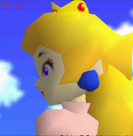
Triangles in the RDP can be shaded. Not only that, but also their shade can change when moving from one vertex to the other, producing a gradient. (Note: the RDP doesn’t really use vertices, it uses edges, see Rasterization) This is great when you have many bits of color to work with, you can get pretty nice gradients:
 |
|---|
| Peach being drawn with 32 bits per pixel. Look at those smooth gradients! |
However using 32 bits per pixels (bpp) is expensive. Many games like Super Mario 64 or Mario Kart 64 would choose to use 16 bpp. But using 16 bpp means that you have access to less colors. You get 5 bits for the red channel, 5 for green and 5 for blue. (The rest are used for coverage, described below). The RDP pipeline keeps individual color component values in 32 bpp precision until the Memory Interface. In order to convert from 32 bpp to 16 bpp, color quantization must be performed. As a result your gradients are no longer smooth. You get what is known as mach bands:
 |
|---|
| Peach being drawn with 16 bpp. Eww, look at all these ugly bands |
To counteract this, the RDP has a mode called dithering. This isn’t something exclusive to RDP, it’s a technique often used when you have access to a limited color palette, but want to create the illusion of higher color depth.
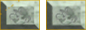
Below you can see an amazing example of dithering:
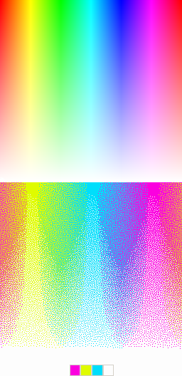 |
|---|
| The bottom image really only uses 4 colors, yet looks like it uses a lot more. Zoom in for yourself to see! |
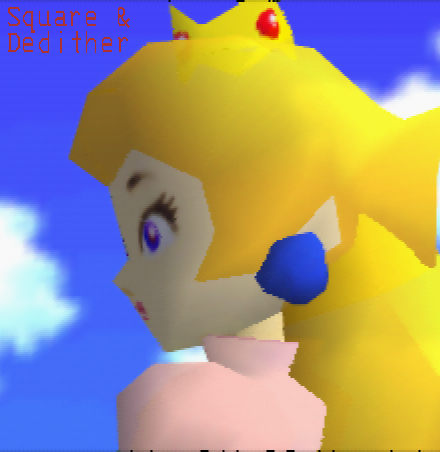
Dithering can be enabled for both color and alpha using rgb_dither_sel and alpha_dither_sel. Here’s Peach from before with the “Magic Square” dithering algorithm applied:
 |
|---|
| Much better! But what are those dots in her hair? |
There’s a total of four dithering modes that RGB can be configured to: “Magic Square”, Bayer, Noise and None. Alpha can be configured to four modes as well: Same as RGB, Inverse of RGB, Noise and None.
Here’s how they look like:
 |
|---|
| The four different dithering modes, dedithering disabled |
Square and Bayer are algorithms. Square is described in the N64 programming manual to be the best when the dedithering filter (explained in the next paragraph) is enabled, while Bayer is described to be the best when it’s disabled. Noise simply adds random noise. This is commonly used as an effect rather than for dithering, but can be used for dithering as well (for example, a TV static effect).
Dithering as you can see however can produce errors - little artifacts like the ones you see on Peachs hair, clothes, crown and face. For this reason, you can enable a post processing filter in Video Interface appropriately named the dedither filter. When enabled, a dedithering algorithm will be ran to perform error correction. This works pretty well:
 |
|---|
| Final product, with dedithering filter applied |
More info on dedithering on the Video Interface section of the post
There’s another type of dithering that is called Gamma Dithering. You enable this from the Video Interface and only when Gamma Correction is also enabled.
I don’t understand gamma dithering enough to explain it yet.
It goes out of the scope of this post.
Chroma Keying
Coverage
In the color buffer, the alpha channel is used to store the coverage value.
Coverage is essentially a value that denotes how much a pixel is covered by the subpixels. Coverage can be used by the blender for antialiasing, edges of a primitive will have a lower coverage than the area of the primitive (which would have a full coverage value).
Since we have 3 bits to work with and actual pixel coverage ranges from 1-15, a mask (0xa5a5, looks like a checkerboard) is used to take into account only half of the pixels subpixels, thus coverage values range from 1-8 (but stored as 0-7 in binary).
How this coverage is written can be configured using the cvg_dest property.
color_on_cvg
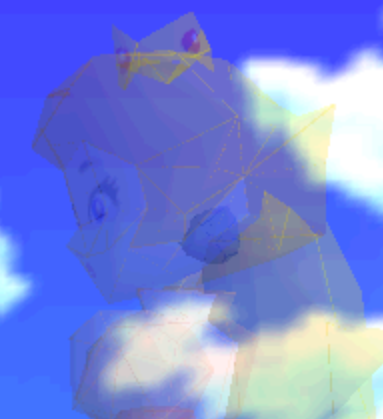
There’s also color_on_cvg. This makes it so that a pixel is only written if the current coverage added to the previous coverage is greater or equal to 8. This helps minimize errors when blending transparent triangles together. For example, Peach when she fades out:
 |
|---|
| Peach fading out with no color_on_cvg implementation |
You can clearly see the edges of the triangles in the above image. This is because the edges here have a low coverage value, which would not otherwise be greater or equal to 8 when added to the previous coverage, so those pixels would not be written to the color buffer.
Depth
The depth buffer is an area in memory specified using the SetZImage command. Whether depth testing is enabled is configured through z_compare_en and whether the depth buffer is updated is configured through z_update_en.
The 14 z bits are not actually the depth value, but a compressed version of the depth value, which is then decompressed to an 18 bit (15.3 fixed format) depth value. I would explain how they are compressed but this post by Kieron does a great job.
After compression that leaves us with 4 extra bits, which is used for the DeltaZ value. The DeltaZ value is important in determining if a pixel is part of the same surface that is stored in memory.
This is how DeltaZ is computed:
\(DzPix= \left|DzDx\right| + \left|DzDy\right|\)
To fit it in the 4 bits, another compression algorithm is used, this one is much simpler:
\(DzMem=\log_2(DzPix)\)
Obviously decompression is the inverse:
\(DzMem_{Decompressed}=2^{DzMem}\)
When computing whether the pixel is part of the surface, the worst case DeltaZ is used:
\(DzMax=\max(DzPix, DzMem)\)
There’s 4 depth testing modes, configured through z_mode
Opaque
This mode does a simple NewZ < OldZ usually. However if coverage overflows it does a different check called “Nearer” (mentioned in “Z Calculation” chapter in the N64 programming manual)
This check is to reduce punchtrough when the new triangle is not part of the previous surface.
 |
|---|
| Edges of triangles look weird without a correct opaque implementation |
Interpenetrating
TODO: explain
Transparent
This is used for transparent surfaces (think water outside of Peachs castle). This is usually used in conjuction with color_on_cvg to avoid internal edges blending twice as mentioned earlier.
The check for this is by far the easiest to implement. If NewZ < OldZ, it passes the depth test.
Decal
This mode is used to render a textured primitive on top of another surface (think a flag for example). This depth test passes when the primitive we are trying to render is coplanar with the surface we are trying to render it on top of. TODO: explain how this is checked
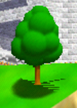 |
|---|
| Tree shadow without a correct decal implementation Normally it should sit nicely on top of the hill but because our implementation is wrong it sort of blends with it. |
Rasterization
The rasterizer uses an edgewalker algorithm to step the primitive slopes and the property (rgba, stw, z) slopes. If you want a peek into a basic implementation and further explanation of how it works, check out my other post on N64 triangles. Note that the implementation on that post only steps the primitive itself, not the properties, and does not implement other important things like subpixels and scissoring.
Color Combiner
The color combiner can combine 4 colors into 1, using the equation (A - B) * C + D.
A, B, C and D can be many different things, and they are configured by the SetCombineMode command
 |
|---|
| How the color combiner picks colors |
There’s also an alpha combiner, which uses the same equation but different inputs:
 |
|---|
| How the alpha combiner picks colors |
Using the color combiner you can (for example) combine texel colors with shade colors, to produce a shaded texture.
The color combiner also has 2 configurable colors, primitive color and environment color, configured through the SetPrimitiveColor/SetEnvironmentColor commands respectively.
Traditionally they are used to set a constant polygon face color or the ambient environment color, but technically the names are arbitrary and they can be used for any purpose.
You might be more familiar with the name the color combiner stages have in the 3DS or in (old) OpenGL: Texture Environments. Of course nowadays we have fragment shaders.
The RDP has an OpenGL 1.1 in a libdragon branch, and you can configure the color combiner in part using glTexEnvi.
Blender
The blender blends the previously combined color with the color buffer color or the blend register color (set by SetBlendColor) or the fog color.
There’s 4 inputs, named p, a, m, b in the manual but let’s name them color 1, multiplier 1, color 2 and multiplier 2. These inputs are specified by the 8 b,m##,# properties, 4 for cycle 0 and 4 for cycle 1.
Color 1 and 2 are picked from the following table:
| Index | Source |
|---|---|
| 0 | Combined color |
| 1 | Color buffer color |
| 2 | Blend color |
| 3 | Fog color |
Multiplier 1 is picked from this table:
| Index | Source |
|---|---|
| 0 | Combined alpha |
| 1 | Fog alpha |
| 2 | Shade alpha |
| 3 | 0.0 |
Multiplier 2 is picked from this table:
| Index | Source |
|---|---|
| 0 | Inverse multiplier 1 |
| 1 | Memory coverage |
| 2 | 1.0 |
| 3 | 0.0 |
The blender output is calculated like so:
\[BlenderOutput = \frac{p\cdot a + m \cdot b}{a+b}\]The alpha channel is not stored in the framebuffer and as we know it’s used to store coverage instead.
Texture Engine
TODO
Texture Filter
TODO
A. References
- N64 programmers manual
- SGI RDP command summary
- n64brew
- Angrylion & paraLLEl-RDP source code
- Nintendo 64 patent
- n64-resources repository by Dillon
- Z format encoding explanation by Kieron
B. Video Interface
The video interface is not part of the RDP but it is important to get an idea of what it does.
It has two main functionalities:
- Drive the Video DAC
- Apply some postprocessing effects
Postprocessing effects
Video filter
Before the blender output is written, if the pixel is not fully covered the video filter algorithm is applied:
\[FinalColor=cvg \cdot BlenderOutput+(1.0-cvg)\cdot BackgroundColor\]\(BackgroundColor\) is a combination of the fully covered pixels in a \(5x3\) area around the current pixel
TODO: The video filter is a bit more complex than that. It’s not just coverage that feeds into it, but the z buffer too (Though I’m not sure about the exact algorithm, it might just use delta-z or both delta-z and depth)
Dedithering
TODO: algorithm